
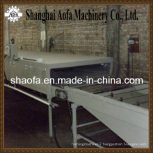


cable tray
Basic Info
Model No.: HZ-300
Product Description


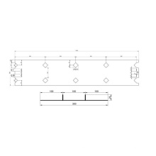
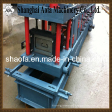
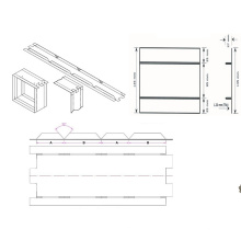
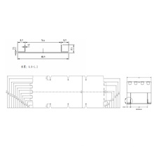
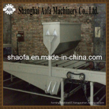
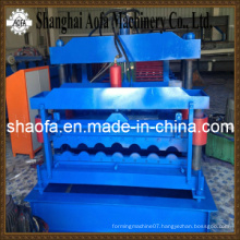
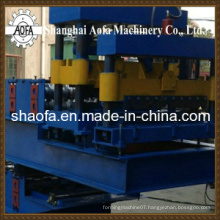
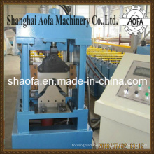
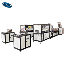
 1. Profile drawing: Finalized in drawing which is approved by both parties 2. Main parameters 2.1 Suitable material: Ø Raw material: Galvanized coil sheet Ø Yield stress: ≤300Mpa Ø Thickness: C-Track 1.25 mm/ C-Track Element 1.25mm 2.2 Technical parameters Ø Air supply: >0.5Mpa Ø Speed: ~10m/min(not include shearing and punching ) Ø Power supply: 380V±10%;50HZ 3. Working flow(as per the layout drawing) Decoilling→Levelling→Roll forming→Punching→Shearing→ Run-out table 4. Machine components:
 No. | Name | Model | Unit | QTY | Remark |
1 | Decoiller | Hydraulic | set | 1 |
|
2 | Straightening | Seven rollers leveling | set | 1 |
|
3 | Lubricating device | wool felt lubrication | set | 1 |
|
4 | Roll forming unit | Column wall | set | 1 |
|
5 | Punching | Fast punching | set | 1 |
|
6 | Shearing | Hydraulic | set | 1 |
|
7 | Run-out table | Simple table | set | 1 |
|
8 | Hydraulic system | Professional | set | 2 |
|
9 | Electrical system | Whole line control | set | 1 |
|
Product Categories : Roll Forming Machinery > Other Forming Machinery
Premium Related Products


Other Products

Hot Products
EPS Sandwich Panel Machine (AF-S1000)C Purlin Roll Forming Machine (AF-80-300)H Beam Welding Lineguard rail forming machineroll forming equipmentDump truckCovering Machinecold steel HVM series High speed roll forming machineEPS sandwich panel machineSIN beam Automatic Welding Linegalvanized sheet slitter making machine/steel plate slitting machineDownspout/downpipe roll forming machine hot sellwall roof tile floor deck panel forming machine floor tile making automatic machineDouble Feeding C U Shape Metal Stud Channel rolling forming machineAdvanced Multi-Model Color Steel Roof Panel Roll Forming MachineAuto Steel Coil Holder/Hydraulic Uncoil With Coil Car 5 Tons